I really HATE saladworks. Like most things i hate, i obsess over it. The altruism in me KNOWs its great, but it actually sucks.
Solidworks is like a the stubborn old man who has worked at the company for longer than anyone knows. They’re very particular in their ways, forcing you to go slow and do it “their way”. But if you work with them, there’s a reason they’re so prestigious, and they get the job done properly in the end.
As much as solidworks gives you options to do things different ways, the software itself runs best using particular practices and workflows. Because of this, shortcuts actually become longcuts.
I try to learn what all i can, survey many opinions, and try to optimize how i use different software. Solidworks is a very complex software with tons of customizability, and it quickly pays off to set it up for how you use it.
1. Solidworks Fundamentals Overview
Basically this part is a more inremediate level “quick start” guide. It’s what I would teach any new engineer out of school or some one already familiar with a 3D modeling software.
Solidworks works with three main file types. They are prompted to you when you open Solidworks.
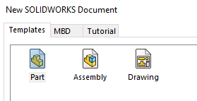
- PART a part is the smallest, most singular component of what you are designing. When you take something apart, and you can’t take the things apart any more, each one is a SW Part. Parts should be a single material.
- ASSEMBLY an assembly is two or more parts. It defines how those parts are oriented and allowed to move about each other.
- DRAWING a drawing uses parts and assemblies to create detailed documentation for manufacturing, marketing, and product literature
Parts
Sketches
- Sketches should be kept simple. Even though solidworks will entice you to try and bake as many features as you can in a single “skeleton sketch”, it dramatically reduces performance.
- Use symmetry. It’s OK to draw full faces and patterns temporarily, but they should be turned to construction lines or trimmed away after sketching, to be mirrored or patterned later
- Constraints >> Dimensions. Often the design intent is much better set as a constraint than a numerical dimension. Numerical dimensions can often be replaced by a construction line and constraints. Any necessary dimension(a physical measure with calipers) really only needs to be input once and should be referenced from there out.
- Fully Defined Sketches. I rarely do it, and I often regret it. I’m alittle embarrassed to be honest, but I’m getting better. Fully defined sketches are completely necessary for any type of shared or to-be-used-later parts. Its also borderline unprofessional and rude in a work setting.
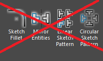
- NO patterns, mirrors, or fillets in sketches. Save these for features. Mirrors are a judgment call of if the easier sketching is worth the lag. Fillets in sketch are OK for raw materials like angle extrusion or for non critical corners. Often you’ll want to keep the sharp corners to reference or mate in the assembly. They will be fillet features later.
Features
- Again use symmetry. Mid-plane extrude should be the default extrude option. A single revolve can replace countless extrudes
- Again, Relations>>dimensions. Use to and from planes instead of blind dimensions
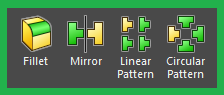
- Mirrors and Patterns. Mirrors and patterns should be done as features vs in the sketch. SW will run much better. Pattern seed only for large patterns.
- Fillets. Fillets should be done as features, and they should be the last features possible. This is so they can be easily suppressed, which keeps the corners for mating.
Assemblies
Assembly vs sub-assembly
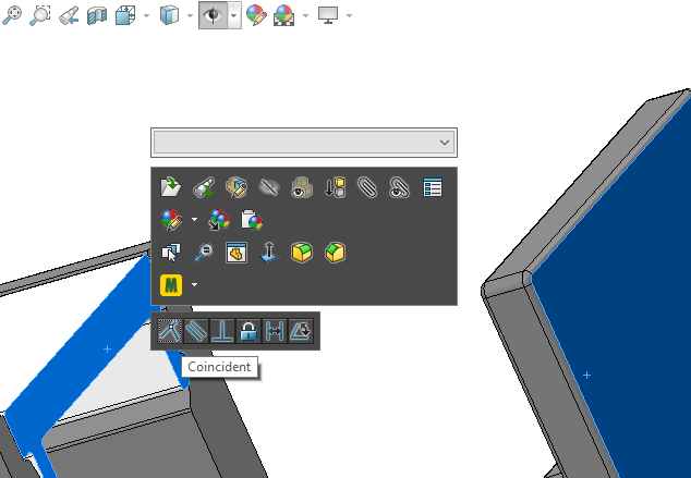
- Holding control while selecting, then releasing control without moving the mouse will bring up a secret quick mate menu.
- Smart fasteners work well
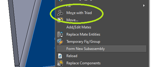
- Move with Triad is a more intuitive way to freely move components. it can only be reached through right click
- Flexible sub-assemblies can be useful to calculate our visualize how odd components may move. Flexible subassemblies, allows any underdefined mates “float” in the parent assembly.
- Start with a large, root or central part. Fix it or mate to the origin planes. Then, mate as many other parts and sub-assemblies as you can to that central part vs creating a daisy- chain of mates and parts
- Assembly visualization is a neat tool
- Click on Part + TAB will hide the part in an assembly
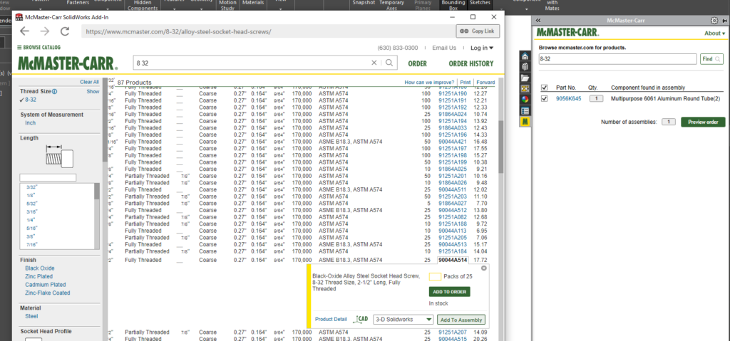
- McMaster Carr add-in is great it allows you to search for a part on McMaster, import it right into SW, and will even keep a BOM running per assembly in case you want to purchase, all in the assembly window!
- a single sub-assembly should only be no bigger than necessary(duh?) The sub-most assembly should have no performance issues.
Drawings
- Leaving an assembly fully shown, and hiding the parts in the drawing view usually leads to less headaches vs Hiding in the assembly before creating the view.
- Linking title block fields to the properties table is extremely helpful especially when you have multiple pages.
- Holding CTRL while dragging a note arrow, will make an additional arrow to flag multiple parts
When i started working at my current
While i probed sales about their workflows, i was also experimenting with engineering softwares and design methods. I wanted try and quantify as many “Features” as i could into this pipeline.
2. Customized Layout and Settings
The default setting and layout for sw is whatever, but I’m sure it can be better for what you use solidworks for. Here is a download for my settings if you’d like to try them. I created these for my own workflow. I wanted to tailor it to these criteria
- Must feel familar enough to default layout to be able to use default in a pinch. I also would like someone familiar with the default settings, to feel naturally already familiar with my mine
- Prioritize latency and stability in exchange for visual performance and feature rich.
- Improve QOL as much as possible
Since ive created my custom settings, I’ve revised them a few times. I’m currently on V3 of my better settings, and i will share the link here.
Visually, it is pretty similar to the default layout, just a dark theme, and a pure white background. Most of the graphical settings are tuned down for faster performance, and the animations are fast to make it snappy. I don’t like when arcs become faceted, so that setting is a bit higher. Beyond that, I deleted most of the tabs and features that I don’t use. Whenever im looking for a button i cant find, i add it to the current tab, even if it is already there or on a different tab.
Some of the QOL settings I love are
- “Auto-rotate view normal to sketch plane on sketch creation and sketch edit”
- “Enable on screen numeric input on entity creation” and “Create dimensions only when value is entered”
- the default STL export settings are a bit coarse so i keep that custom
I encourage everybody to experiment with their layout and customize it to their own workflow.
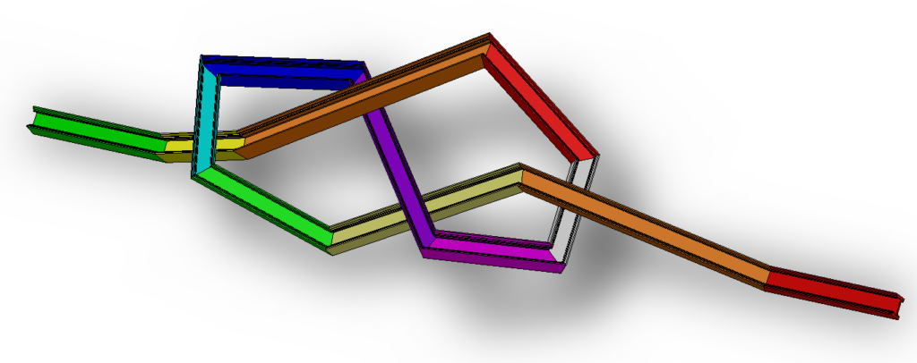
3. Weldments Workflow
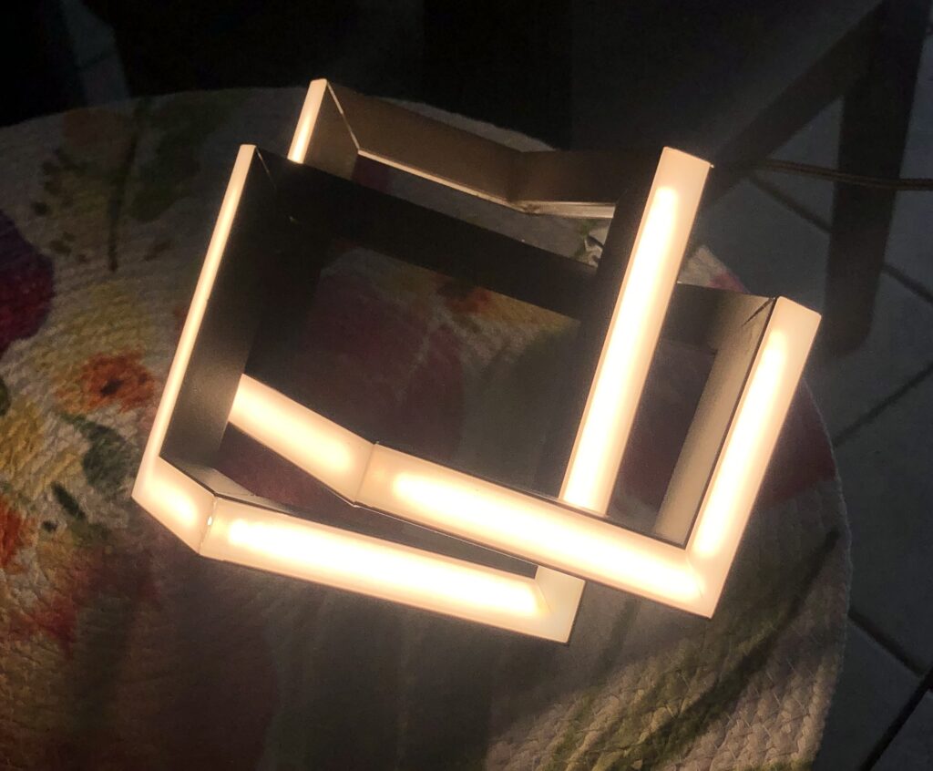
One of the solid works features I’ve used and researched the most are the weldments tools. The Weldments tool helps you manipulate parts that are typically made or supplied as with an extrusion process. Since i work in the linear architectural lighting industry, i deal with many many different extruded profiles. Weldments allows me to use an identical workflow, regardless of what shape or orientation a particular profile might be.
I have used this along with some other techniques to refine a workflow and optimize efficiency holistically through the company. By holistically, I mean this process starts when the customer sends the first dimension, and it ends, kind of never. Crucial data about a past job may be relevant years after shipment.
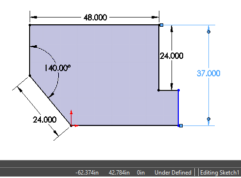
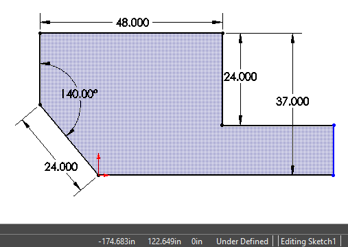
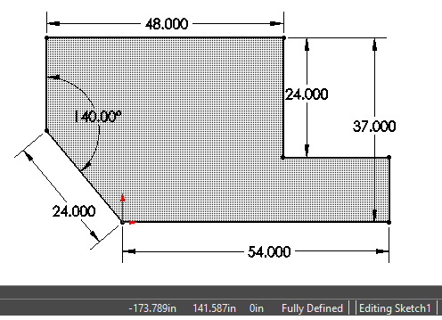
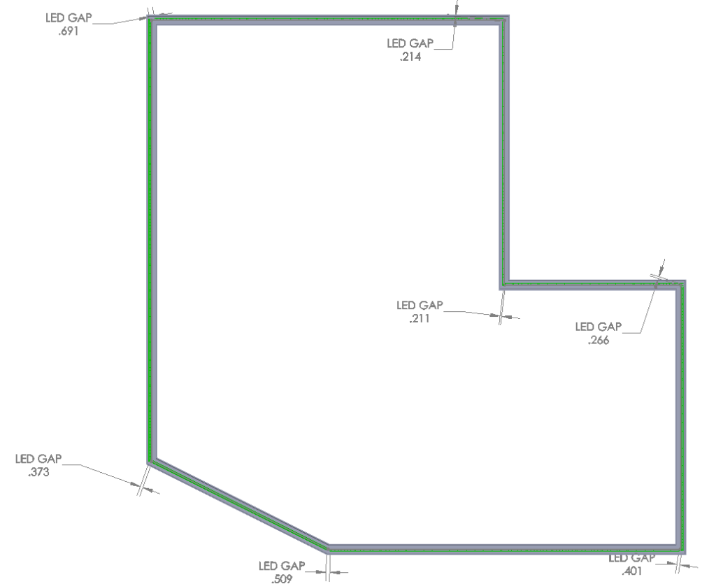
- Defined layout dimensions and corners
The first step is to get enough information to be able to propose a layout. The beauty of this step is that after importing the info into sw, a quick visual indicator will tell if enough dimensions are provided or not.
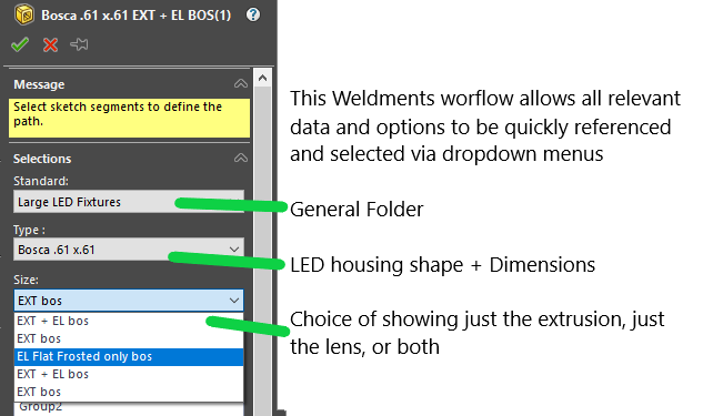
2. Client preferences
next step is to input the options and preferences of the client. Things like,
- which shape light and lens
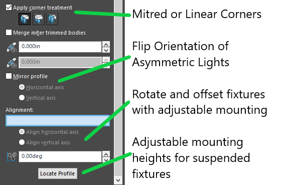
- Is the lighting on a wall or on the ceiling?
- is the lighting on the surface, or recessed flush, or offset a certain distance
- what color LED and finish
- How are the corners to be treated
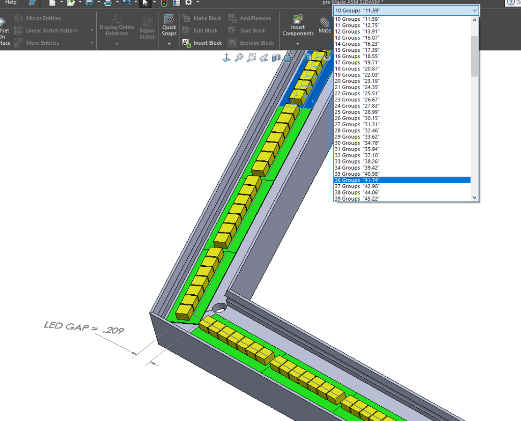
3. Layout Led
The next part is to insert models of the different LED flavors and sizes to see how they fit best. This is a intuitive and error proof way to ensure there are no surprises during manufacturing.
I used the power of design tables to automatically incorporate all of the different LEDs and electrical properties(for drawings and reference). This is a super quick way to reference important data without having to open a spec-sheet.
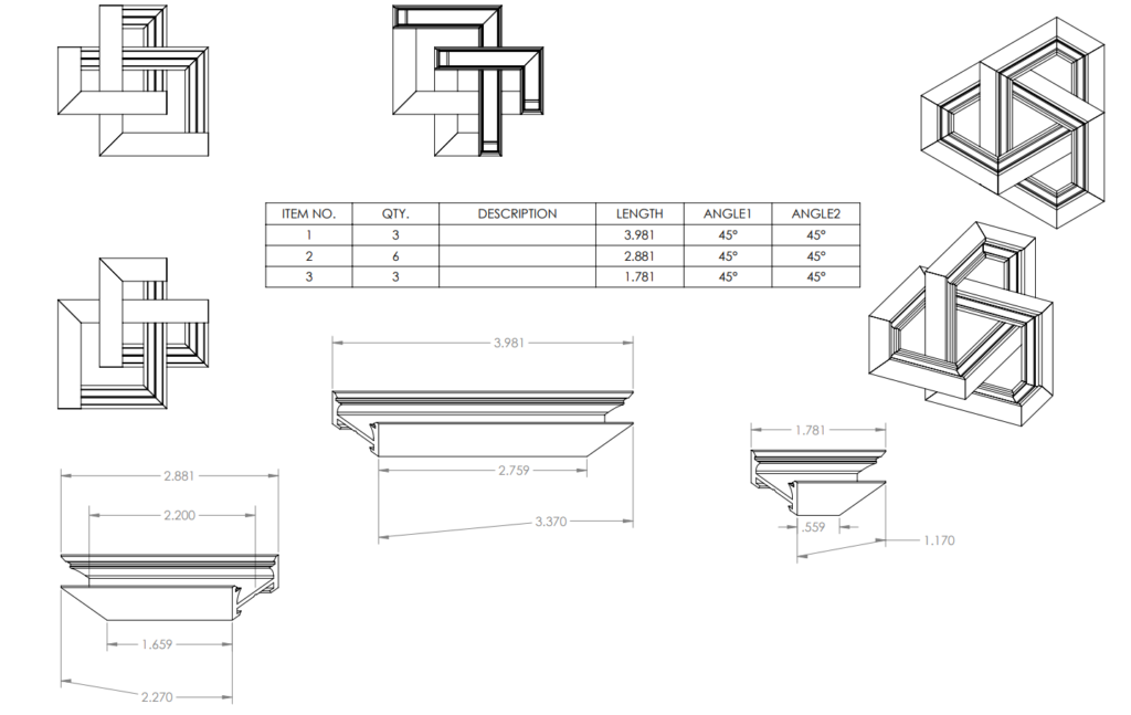
4. Cut extrusion
Now that we see where the LEDs need and can be cut, we can cut down the housings and lenses to make manufacturing and shipping reasonable.
5. Power feed holes, end caps, and special features
This is where common power feed or endcaps can drive part numbers in the BOM. Again, no better way to keep track while automating. This helps keep all the different options different while combining similar parts.
6. Make drawings
Now that everything is set up cleanly in the software, it makes creating the drawings a breeze. Ive set these up with 2 types of drawings in mind, sales drawings for the client, and manufacturing drawings for assembly.
7. Sales drawings can now quickly be shown in 2D and 3D views
Colors can be easily added and changed if needed. Showing additional mounting accessories and hardware is as easy as solidworks let’s it be.
BOMs and tags are automated, with quick options for additional info such as Run ID#, wattage, and reordering bom items. Identical fixtures like corners, or longer runs can be congregated into multiple QTY of a single line.
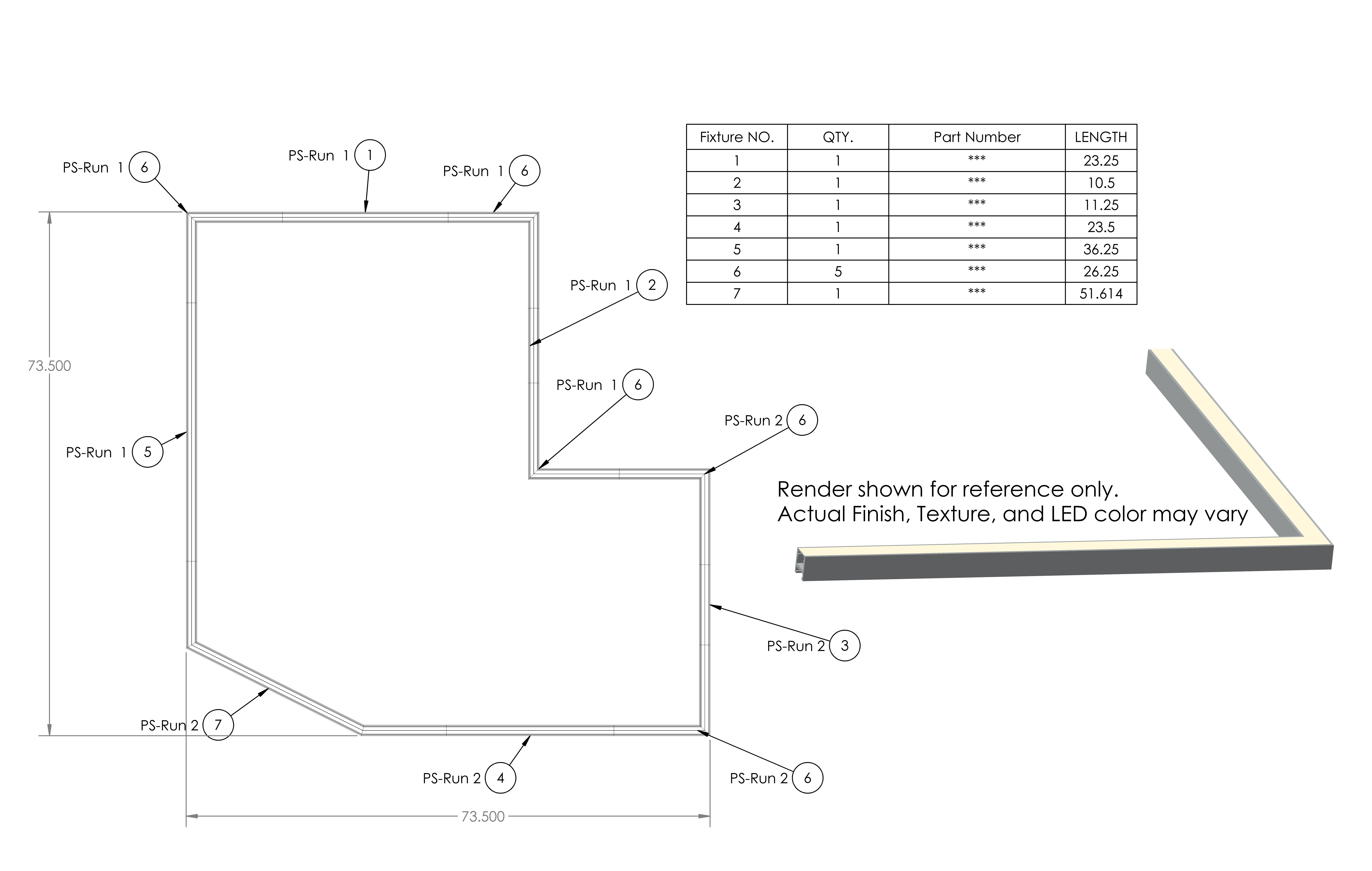
8. Manufacturing drawings are just as swift.
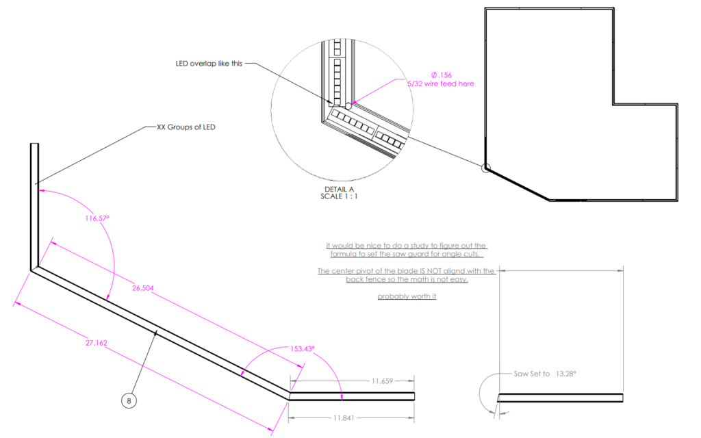
Just a different set of features. Cut lists can be automated to show lengths and dimensions concisely. Special miter and fabrication details can be called out per part. LED count and special notes to builders.
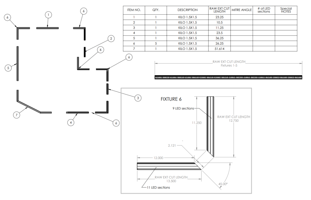
Specific callouts and notes are crucial for custom builds. Standard production is made to specific, unwritten dimensions, anything deviating from that needs attention.
9. This workflow was designed to be generic and procedural.
It provides a solid method for generating complex LED linear lighting layouts. It favors revisability and detail tracking over speed and familiarity.
10. File Transfer
An additional benefit of this procedural workflow is that at any point, documentation can be created and passed off amongst teams in their preferred file types.
The power and potential of this is extraordinary, and I guess that’s why solidworks has the traction they do. Combing this with the calculation abilities of Assemblies, can really expand what is practically manufacturable.

Ask me any questions you may have or share what you want to see next!